INSTALLATION PRINCIPLE
EKOGRID™
INSTALLATION PRINCIPLE OF THE GRID AND TRANFER PULSE
-
Cost effective installation of electrodes and cabling
-
Low energy consumption
-
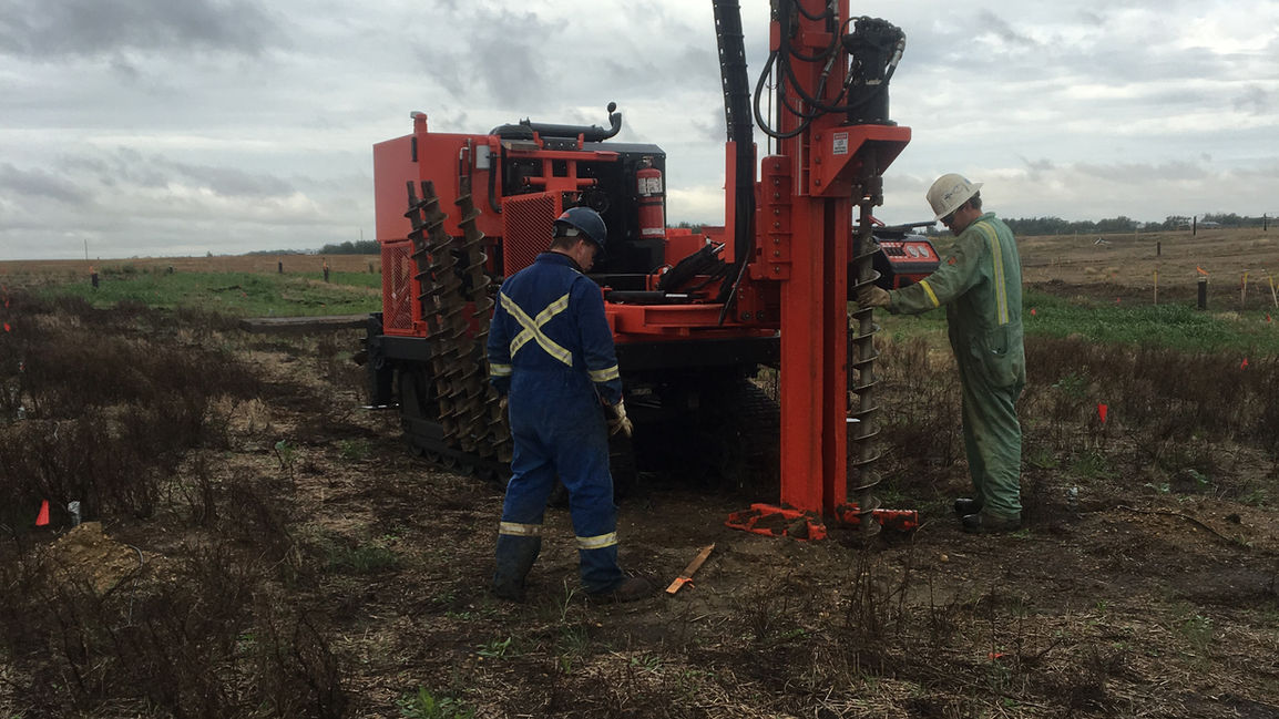
Perforated pipe can be used as electrodes and as an injection point for bio-remidiation agents, as well as water sampling points
-
Electrode spacing typically 5 m
-
Pulsed current goes through polluted soil (marked reaction paths), and oxidizing chemicals are formed by electrochemical reactions at particle surfaces
-
EKOGRID™ transfer pulse can transport water and water soluble compounds in the soil and groundwater between the electrodes

EKOGRID™ Electro Osmotic Transport
-
In normal remediating mode EKOGRID™ pulses are equally timed to both directions between the electrode rows
-
The low voltage current makes the charged contents of the pore water move back and forward with short electro-osmotic pulses
-
EKOGRID™ control unit can be used in transfer mode, where longer pulse to one direction is applied
-
Transfer mode utilizes electro-osmosis to move soil cations and water with everything water soluble

-
DRAWING A – Drill tube electrodes with perforation at the depth of GW layer
-
•Water and nutrients pumped via electrodes, optimally to every second electrode row first and then to the other rows
-
•When injecting (water and nutrients pumped to tubular electrodes) EKOGRID™ electric field is adjusted for transfer pulse (e.g. 6-24 hours with longer pulses to one direction)
-
•When not injecting the normal symmetric EKOGRID pulse for induced electrolysis is used.

-
DRAWING B – Drill tube electrodes with perforation both in unsaturated and saturated zone
-
•Same as in option A, but injection system extended to the unsaturated zone
-
•Solution is recommend if targeted contamination is mostly in both saturated and unsaturated zone


